LED Hexagon
A wall mounted lamp using NEOPIXEL LEDs to create different patterns.
Intro
I wanted to make the wall in my living-room a bit more interesting by building some sort of wall light/artwork. For that purpose I decided to make use of a couple meters of NEOPIXEL-LED-Strip I had bought recently.
Regarding the shape I started with a large Hexagon (because Hexagons are the Bestagons). However, I was worried that it looked a bit too boring and did not allow for many cool animations. Therefore I decided to connect 3 of the corner with a Y-segment, thus creating a shape that resembles three conjoined rhombuses.
Dimensions
For my application I needed to fill the space between my living room table and my ceiling, which is about 140cm. Therefore I decided that the light should have an approximate height of 130cm. The aluminium segments have to be slightly less than half of that (as the connectors take up some space as well), and I decided to go for approximately 63cm arm length.
Parts
I wanted to keep this project as simple and cheap as possible. Therefore the goal was to keep the part count as low as possible. I bought the following parts:
- 3x 2 Meters of Aluminium U-Section (Dimensions: 15mm x 19,9mm x 2000mm)
- 6 Meters of WS2812B LED Strip (these are off-brand NEOPIXELs with 60LEDs/m)
- Arduino Nano 33 IoT
- 3x I2C 3.3V to 5V Level Shifters
- Generic 5V/10A Power Supply
- 1kg of matt black PLA
- One can of aluminium primer
- One can of matt black paint
- Some pieces of cable
Construction
1. First of all, I cut the Aluminium U-Sections to the correct lengths of 63cm, resulting in 9 arms of equal length. Using the primer and black matt spray paint, I painted them to the desired color. I made sure that there was no overspray to the inside of the U-Section and only the outer layer that is visible, is painted.
2. The connectors are 3D printed using generic black matt PLA. I printed them on a powder coated PEI printbed and made sure that the print sticks well. The bottom of the print is at the front, so a good result of the first layer is somewhat important. There where 4 different kind of Connectors I had to print:
- 1x 3-Way Center Connector – It sits in the middle and holds the Arduino Nano 33 IoT as well as the I2C Level Shifters
- 2x 3-Way Corner Connectors – Used for the top right and left corners
- 1x 3-Way Corner Connector with Cable Mount – Used for the bottom corner holding the cable
- 3x 2-Way Corner Connectors – For the corners that only join two arms
- 9x Rear Lids – These are glued to the back and close the connectors
- 1x Power Supply Housing and Lid
Files:
3. On a large piece of cardboard forming a flat surface I used glue to mount the Aluminum arms to the Connectors. I had the open section of the U-Profiles facing up, so that the painted surface is facing the floor.
4. Using the sticky tape supplied with the NEOPIXELS I glued the LED strips into the Aluminium channels. I cut all the strips to the same length beforehand and made sure that there is the same number of LEDs on all the segments. For the segment length I chose, the correct amount of LEDs was 38.
IMPORTANT: The orientation of Data Transmission on each strip of NEOPIXELS is important, as they have a DATA INPUT and a DATA OUTPUT. Usually a small arrow or the label DI (Data Input) and DO (Data Output) show the direction the data travels.
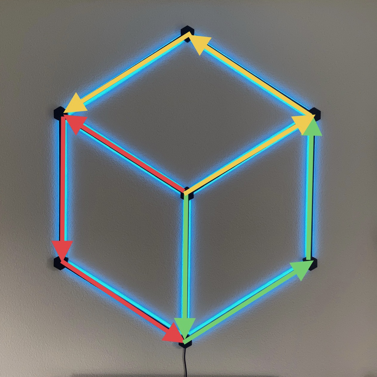
The orientation for each strip should be in a similar manner as shown in the picture above. The data is traveling in the direction of the arrows. Each color represents one section of 3 segments that will have their data outputs connected. Each section will have 3×38 LEDs each, resulting in a total of 114 LEDs per section (or 342 LEDs for the whole lamp).
5. Soldering the NEOPIXEL Strips to each other was the most tedious step in the whole construction. To explain it a bit easier, I split the steps up for the different connectors:
- 3-Way Corner Connector with Cable Mount at the bottom: I soldered the 5V and GND pins of each strip to each other, as well as the 5V and GND from the power cable. I also connected the DATA OUT and DATA IN between two of the three strips (don’t connect the DATA OUT of the 3rd strip, which is the red arrow in above picture, to anything!).
- 3-Way Corner Connectors at the top right and left: Connect the 5V and GND pins of each strip to each other. Connect one DATA OUT and one DATA IN. One of the strips should have a DATA OUT that is not connected to anything (green arrow at the top right corner in the picture and yellow arrow at the top left corner).
- 2-Way Corner Connectors: These are easy, as they only require a connection of all the pins (5V, GND, DATA OUT/IN) between the two strips.
- 3-Way Center Connector: This is the hardest connector to solder, as it requires 5V to be connected between the three strips, as well as the I2C Level Shifter’s 5V input and the Arduino’s Input. Same thing for the GND pins. Additionally you need to connect the DATA IN off each of the three LED strips to one separate output of the I2C Level Shifter. Finally connect one I/O Pin of the Arduino to one input pin of the I2C Level Shifter as well as the 3.3V output from the Arduino to the 3.3V input of the I2C Level Shifter. It is a tight fit, but it is possible to get it all done. Remember, it doesn’t have to look pretty, it just needs to work!
6. After finishing the solder joints, I used a digital multimeter to check for any short circuits and continuity – You can skip this step if you are feeling extra lucky! Afterwards, I ran a quick function test to make sure all the LEDs work.
7. Before mounting the rear lids, I used some more glue to fix most of the cables inside the connectors in place. I also fixed the I2C Level Shifter as well as the Arduino in place inside the Center Connector. Make sure that you can still reach the USB port of the Arduino! I arranged the Arduino vertically, so that the USB port is facing the bottom arm. If everything is done, I used some more glue to mount the rear lids and fix the arms in place once more.
8. After the glue has set properly, I used the cardboard I assembled the Hexagon on, to flip it into the vertical and hang it up on a wall. The construction is fragile, especially while flipping from one orientation to the other. Once vertical, it should be able to hold it’s own weight if it is supported at the top 2-Way Connector.
9. For the 5V/10A Power Supply I 3D printed a simple housing. It has a provision for a 12mm switch as well as cable holes for both the 230V input cable as well as the 5V output cable. Some air-holes allow for heat dissipation.
Programming
After mounting the LED HEXAGON on a wall, it is ready to be programmed. First of all, I added the Arduino OTA Library (Over-The-Air Library) to the code, to allow it to be programmed remotely. I also made sure that the Arduino Nano 33 IoT automatically connects to my home WiFi. After doing all that, I do not have to access the physical USB port on the wall lamp anymore, to upload an Arduino Sketch.
To drive the NEOPIXELS I use the FastLED Library. The Adafruit NEOPIXEL Library also works well, however the FastLED Library has some additional features that I found very handy (for example, to manage the maximum power draw).
More details on programming, as well as the source code will follow at a later date, once the software is completed. Thank you for your patience!
Final thoughts
While the software is not yet completely finished (will it ever be?), the construction itself is finished. Currently I have implemented different patterns and animations, ranging from slow color cycles to fast light motion. The WebUI allows switching between different patterns, speeds and colors from any smartphone in my home network.
So far I am happy with how I turned out. If I ever do a version 2, I would look into adding some sort of diffusers to the Aluminium U-Profiles, as currently the Light output has a sharp edge to it, before it transitions into a more diffuse color gradient. Does not look too bad however, so I am not going to change it on the existing LED HEXAGON anymore.