Part 2 – Battery Redundancy Circuit – Design
Designing and building a redundand power supply for medium sized drones.
Requirements for the Battery Redundancy Circuit (BRC)
Part 1 – Introduction explains why an electronic circuit is advantageous for increasing the redundancy of a dual (or multiple) battery setup in a drone. This part explains the design requirements for such a circuit and describes the chosen layout for the battery redundancy circuit to be used on the HEXACOPTER-project.
Before starting with a detailed design, some key parameters must be defined:
- Amount of Batteries
While a 3 or 4 battery design are certainly useful for some designs, a pretty high amount of redundancy can be achieved with just 2 batteries. For this project this is sufficient and the design will make use of a maximum 2 batteries connected to a single board.
- Voltage capability
Voltage limits are defined by the batteries that are used or might be used. Generally being able to handle 2S-6S LiPo batteries is sufficient for most applications. This results in a minimum voltage of 6.5V for a fully discharged 2S battery and a maximum voltage of 25.2V for a fully charged 6S battery. With some margins the values are 6.0V to 28.0V respectively.
- Current capability
The amount of Power the target drone consumes is a huge factor in designing the battery redundancy circuit (BRC), as the active and passive components in the circuit have to handle the load.
For the HEXACOPTER project, a hexacopter drone with a total weight of approximately 4-6kg class, the T-MOTOR Antigravity 4006 motors (with 14*4.8 carbon fibre props) will be used. The data-sheet of the motor provides valuable information:
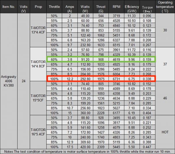
Marked in green is the motors running at 60% throttle and providing about 908g of thrust each. This will be referenced as Burst Power henceforth.
Marked in red is the motors running at 100% throttle and providing about 1975g of thrust each. This is the Nominal Power level of the copter.
At the Burst Power setting (100% throttle), the motors draw 12.2A each. This means that the total current is 73.2A for all six motors. Together with the onboard electronics the total current the drone draws is at around 80A depending on the payload. To allow for a further upgrade to larger props, the maximum Burst Power current the BRC will be designed for, is 90A. Burst Power will be limited to short periods of less than 1 minute with 2 minute recovery breaks in-between.
However, in normal operation the drone’s motors are rarely at 100% load continuously. During a hover the drone has to counteract its weight, which for a design weight of about 5kg would result in a Nominal Power setting at around 60% throttle. This causes the motors to be much more efficient, resulting of a power-draw of approximately 3.8A each. This means that the total current consumed by the motors is around 22.8A. Adding another 7A for onboard consumers and some further power reserve for small maneuvers as well as future upgrades, the Nominal Power consumption is at 45A. The BRC should be able to handle this current continuously throughout the whole flight.
- Other
After eliminating the single point of failure posed by a single battery, it is key not to introduce a new one by designing the BRC in such a way that a single component failure results in a loss of the drone which would negate any reliability benefits created by the BRC.
- Summarized
The following design goals and limits summarized:
– Prevent batteries exchanging charge from one to the other.
– Isolate a battery in case of an internal short.
– Allow for equal discharge from both batteries.
| Limit | Minimum | Maximum |
|---|---|---|
| Battery count | 1 | 2 |
| Voltage | 6.0V | 28.0V |
| Current – Nominal Power | 0A | 45A |
| Current – Burst Power | – | 90A |
Choosing components
- Basic Circuit Layout
After figuring out the requirements of the BRC, the basic layout is the next logical step. This allows for the selection of the right components.

The basic design is simple and does not even require any advanced electronics like logic chips or even a micro-processor, as all the desired functions can be achieved by a simple diode circuit.
- Diodes (or not)
As pictured above, Diodes would provide an easy solution for the needs of the Battery Redundancy Circuit. However, they are not ideally suited for this application.
The main issue is the voltage drop across most types of diodes. Schottky-Diodes, usually the go-to for high current applications, feature an extra low voltage drop compared to conventional diodes. Still, at 50A, a drop of 0.8 to 1.1V can be typical. Theoretically this drop can be improved by adding more diodes in parallel, but at a lower 20A, 0.6 to 0.9V drop is still a problem. Usually the drone’s electronics can compensate for the lower voltage without much issue, however the power lost to heat in the diodes is both bad for efficiency of the UAV as well as not ideal in therms of cooling.
Splitting up the 90A power draw during Burst Power consumption across 5 Schottky-Diodes, each passing about 18A of power with a conservative drop of 0.7V would mean that about 14W of power are lost by each diode for a total of 70W. To dissipate that energy a large and heavy cooling system would be required, which is pretty useless for a drone.
At the desired Nominal Power of 50A, the same calculation likely results in a total power loss of around 35W, still way too much for high efficiency and almost impossible to cool during flight.
Therefore it becomes apparent that the theoretical diode that is required for the BRC must be replaced by something better…
- (Almost) Ideal Diode
By using a P-Channel MOSFET as well as some clever power management chip called LTC4412 it is possible to create a near ideal diode, which is suited for our application.
The LTC4412 chip controls the P-Channel MOSFET and compares the voltages on both sides of it. If the battery-voltage drops below the highest voltage, the MOSFET is turned off, thus preventing any charge flowing into the dead/discharged battery.
Each input of the BRC has its own dedicated LTC4412 chip, therefore keeping the design requirement of not creating a new single point of failure. Even if both LTC4412 chips were to fail, the internal Diode of the MOSFETs would still allow power to go from the battery to the drone, however with a higher loss and increased heat generation inside the MOSFETs – while not ideal, this would at least allow for a controlled emergency landing rather than a crash if signaled and detected to the operator.
- P-Channel MOSFET
The BRC requires some kind of logic to enable/disable the output of the batteries.